Every process has a bottleneck which is the slowest.
The key to improving performance is to find the bottleneck and to increase its output.
This article focusses on line throughput increase within manufacturing facilities; for an example in document processing click here.
Useful Templates
Below are two spreadsheets, one is a blank Pareto analysis sheet with an action tracker and the other is a worked example so you know how to use the blank.
Theoretical vs. Actual bottleneck
The theoretical bottleneck is the process which has the slowest design capacity which may or may not be the same as the actual bottleneck.
The actual bottleneck can be different from the theoretical one depending on the how the other parts of the production line perform. Some of the performance elements to look out for are:
- Defect rate: defects will need to be re-worked or scrapped which is a limit on number of good pieces produced
- Down time: This can be from breakdowns, change overs, proactive maintenance requirements
- Material availability to be processed
- Buffer space to absorb minor stops elsewhere to allow the bottleneck process to keep running
Once you have found the bottleneck process, the aim is to have it running as much as possible; if you lose 1 minute at the bottleneck, you can never recover that time.
We will follow through an actual example of increasing capacity of a production line using simple, low cost solutions.
The only reason you can get to simple, low cost solutions is to dig right down in to the detail so you fully understand the system better than anyone else.
Example production line:
Let’s say that your production line has 5 steps as shown below:
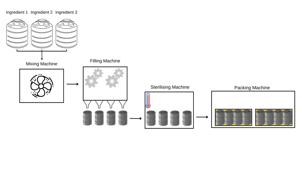
The 5 elements of the production line (and their theoretical throughput) are:
- Ingredient delivery – 1,000 Kg /Hr
- Mixing – 800 Kg/Hr
- Filling – 700 Kg /Hr
- Serilising – 850 Kg/Hr
- Packing – 1,100 Kg/Hr
Building the (theoretical) bowtie
The bowtie is a simple way to represent capacity of a production line (or series of processes).
Each section of the bowtie represents a process step and has both a theoretical and an actual capacity.
Put in to the bowtie format, the line now looks like this:

It is now easy to see which process is the theoretical bottleneck based on design capacity. Theoretical capacity is the processing speed of that part of the line had infinite product to process, infinite space to put the processed parts and never broke down.
Now then, what is the theoretical maximum output of the production line?
700 Kg/Hr.
This means that every other process, upstream and downstream of the bottleneck won’t run for a whole hour. Let’s add average hourly run time for each process to the bowtie:
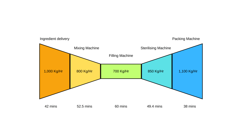
The above now shows the hourly uptime required for each process to match the throughput of the bottleneck. Thus, if you lose 1 minute at the ingredient delivery machine, it will be able to make up for that lost time as it has spare capacity.
The Filling machine however has no spare capacity and 1 minute lost at this process can never be recovered.
Building the (actual) bowtie:
Now let’s add another layer of complexity to this production line.
Let’s say that you take a look at the actual throughput of your production line and realise that your throughput is actually closer to 450 Kg/Hr; far below the theoretical 700 Kg/Hr that your line was built to deliver.
To figure out where the problem is, you can start at your bottleneck process and gather some more data. This can be done quickly by standing at the process with a stopwatch and record the down time and why it stops.
Uncovering main down time reasons:
Step 1:
Print out a copy of page 1 of the Pareto blank template (above) and take that to the line with you.

Step 2:
Fill in the sheet with down time data and add your own D/T reason codes (you get these from observing why the process stops).

If the filling machine stops because product has nowhere to go, then the problem is downstream and if it stops because it has no product, then the problem is upstream.
The longer you spend watching the process and gathering data in this way, the more you will observe and the more accurate data you will gather about the machine stops.
Step 3:
Enter the data you have recorded in to the Pareto blank document on your computer.
Go to the second tab, right click anywhere in the table and then hit “Refresh”.

Step 4:
Note the top reasons for the down time.
In the example sheet, the top 3 reasons for down time are:
- No product (NP) – 45 mins
- Change over (CO) – 30 mins
- No buffer space (NBS) – 15 mins
If the main reasons for stoppages are upstream or downstream, then repeat steps 1 – 4 on the processes either side of the theoretical bottleneck to do a deep dive in to those processes to understand what is restricting the throughput.
Step 5:
Once you are sure you have uncovered the top reasons for the bottleneck stoppages, fill in the action tracker with specific steps you will take to eliminate or reduce this down time.
The new bowtie:
So you now realise that a big part of the down time is coming from one (or several) of the previous processes. You repeat the steps 1-4 above and your data suggests that the whole time spent waiting for product is from the mixing step.
The new line bowtie now looks more like this:
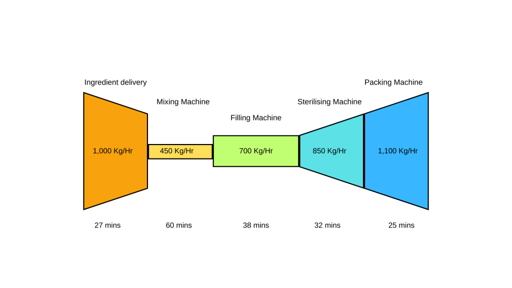
As you can see the bottleneck is now the mixing machine and all of the other processes now have to run even less time each hour to keep up with it.
The Devil is in the detail:
Now the best bit starts!
From your analysis of going through the steps 1-4 above on this process, you note that on average, the process is stopped for the following periods each hour:
- Hot water delivery – 15 mins / Hr
- Mixing time – 10 mins / Hr
Hot water delivery:
Drilling down further as to why you are waiting for hot water, it becomes clear that the hot water feed is shared with another production line that takes priority AND the heating method is slow (heating jacket surrounding a pipe).
The solution?
- Give that process it’s own hot water feed that is independent of any other line or process
- Change the heating method from a hot water jacket to direct steam injection using a hydrothermal valve
Mixing time:
The mixing time is fixed by the R&D department and would require new equipment and potentially a larger tank to do this (both of which are very costly).
After some research, it turns out that the pump that delivers the mixed ingredients to the next process doubles as a high sheer mixer.
The solution to reduce mixing time?
Add a valve to the existing pipework to put in a recirculation pipe back in to the tank. As the regular mixer does its work, the pump will mix the product and put it back in to the tank. Not only does this reduce your mixing time but it also allows you to increase the capacity of that process to compensate for the product recirculating in the pipework.
Now repeat:
Once this is done, you can go back through the process of timing each process to determine which is your new actual bottleneck.
It’s possible that it matches up with the theoretical one but in any case, you now have the framework to go through the new bottleneck to free up further capacity.
